In this Catia v5 tutorial, we will be going over the Multi-Section Solid  and the Shell
  tool. The Multi-section Solid tool is very useful if you are want to create parts which has organic shape to it. The Shell tool on the other hand, is useful to quickly create hollow parts which have constant wall thickness.
To start off, open up a Part Design window in Catia v5. First, create three planes along the x-axis, 3-inch away from each other like so.

Enter Sketch on the original yz-axis and create a 3-inch diameter circle, followed by a 1.2-inch diameter on the second plane, 4-inch diameter circle on the third plane and finally a 2.5-inch diameter circle on the last plane. Ensure that all of the circle are centered at the origin for simplicity purposes.

Now enter Sketch on the first sketch that was create earlier and create two points along the circle using the Point by Clicking  tool. Make sure that the points are align with the the zx-axis (It doesn't which axis the points are aligned with. You just have to make sure that future points created are aligned with the same axis that you have used for the first circle).

Now do the same for the other circles too. These points will be used as an anchors for the guidelines that will be used by the Multi-section Solid tool later.

Once you have create the points on all of the circles, enter Sketch on the zx-axis. Select the Spline tool and create a spline with four points above the circles. Next, use the Constraints Defined in Dialog box tool to coincide the points as labeled in the image below (Point 1 with point 1, point 2 with point 2 and so on).

After you are done with that, exit the workbench and re-enter Sketch on the same axis. Create another spline below the circles and repeat the same steps with coinciding the points from the spline to the circles. What you have now is a wire-frame for creating a Multi-section Solid of your vase.

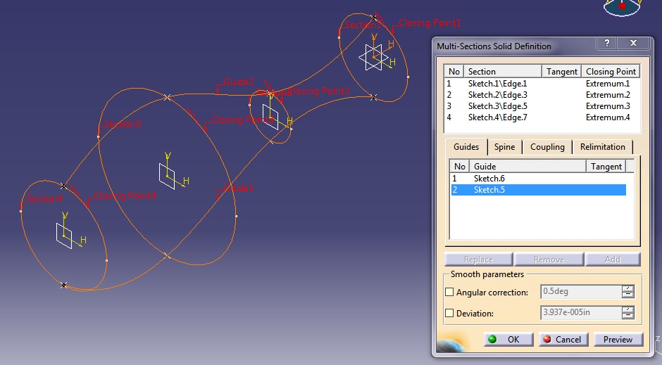
Select the Multi-section Solid tool and a Multi-section Solid Definition window will appear. You will see two white boxes. In the top box, you will want to select the four circles. After selecting the four circles, make sure that the red arrows (circled in yellow) are pointing in the same direction. This step is very important. If the red arrows are not pointing in the same direction, you will be getting a loft operator error message.

In the second box, select the two splines as the guides for this Multi-section Solid. In order to access the second box, just click anywhere on the white space within the second box.

You can now either click Preview to view the outcome before accepting the Multi-section Solid or click OK to just accept the outcome.
You have now created your vase. However, what use is a vase if you cannot put things in it? To create the hollow area in the vase, all you need to do is use the Shell tool. Select the Shell tool and in the Shell Definition window, select the surface at the mouth of the vase as the Faces to Remove.

You can set the Default inside thickness and Default outside thickness to any measurement that you desire. For the purpose of this tutorial, I set the Default inside thickness to 0.05-inch and left the Default outside thickness as 0-inch. Once that you are done, just click the OK button and your vase is finally completed.

I hope that you found something useful in this tutorial. Make sure to check back for future updates in Catia v5 Tutorial for Beginners.

Once you have create the points on all of the circles, enter Sketch on the zx-axis. Select the Spline

After you are done with that, exit the workbench and re-enter Sketch on the same axis. Create another spline below the circles and repeat the same steps with coinciding the points from the spline to the circles. What you have now is a wire-frame for creating a Multi-section Solid of your vase.

Select the Multi-section Solid tool and a Multi-section Solid Definition window will appear. You will see two white boxes. In the top box, you will want to select the four circles. After selecting the four circles, make sure that the red arrows (circled in yellow) are pointing in the same direction. This step is very important. If the red arrows are not pointing in the same direction, you will be getting a loft operator error message.

In the second box, select the two splines as the guides for this Multi-section Solid. In order to access the second box, just click anywhere on the white space within the second box.
You can now either click Preview to view the outcome before accepting the Multi-section Solid or click OK to just accept the outcome.
You have now created your vase. However, what use is a vase if you cannot put things in it? To create the hollow area in the vase, all you need to do is use the Shell tool. Select the Shell tool and in the Shell Definition window, select the surface at the mouth of the vase as the Faces to Remove.

You can set the Default inside thickness and Default outside thickness to any measurement that you desire. For the purpose of this tutorial, I set the Default inside thickness to 0.05-inch and left the Default outside thickness as 0-inch. Once that you are done, just click the OK button and your vase is finally completed.

I hope that you found something useful in this tutorial. Make sure to check back for future updates in Catia v5 Tutorial for Beginners.


