Tuesday, July 3, 2012

Catia v5 Tutorial: Measurement Units and Grid Spacing

The default measurement unit that comes with Catia v5 is in milimeters (mm) and the spacing for the grids are 1 mm for major grid lines (or also known as Primary Spacing) and 0.1 mm for minor grid lines (or Graduation).

However, as you may have noticed, the Catia v5 Tutorials that is available here uses inches (in) as their measurement unit. In order to adjust the measurement unit to the one that you desire, all you have to do is to access the Options window located under the Tools menu.


In the Options window, select Parameters and Measure which in located on the Options tree. In there, select the Units tab and you will be presented with all the parameters available in Catia v5. Select the parameter that you want to adjust and for this tutorial purpose, we will be changing the units for Length. Once you have selected a parameter, you can change its units by using the drop down menu.


In the Sketcher menu, under the Mechanical Design tree, you can adjust the Primary Spacing and the Graduation values to suit your preference. As mentioned earlier, Primary Spacing is basically the length of each major grid lines while Graduation is the spacing between minor grid lines.


As you can see below, I have set my Primary Spacing to 1-inch and the Graduation to 10. This basically means that the length of my major grid lines will be 1-inch while the minor grid lines are 0.1-inch.


I hope that you found something useful in this tutorial. Make sure to check back for future updates in Catia v5 Tutorial for Beginners.

Catia v5 Tutorial: Pattern and Mirror

In this tutorial, we will incorporating several tools, which had been gone over in previous tutorials, into one part.

In addition to that, we will also be covering two new tools in this tutorial. The Pattern  and the Mirror  tool.

As in previous tutorials, we will still be working in Part Design. We will start by creating a 5-inch by 5-inch square in Sketch on the xy-plane. For this square, make sure that one of its corners coincide with the origin of the axis.


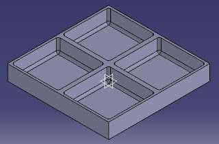
Exit the workbench and create a Pad of 1.5-inch. Next, we will create the feature in the following image on the box that we have just created.


There are two simple ways to create this. One way is using the Pocket tool and the other is to use the Shell tool.

To use the Pocket tool, you will need to create a sketch on the top surface of the box. Just select the Sketch tool and select the top surface as the plane for your sketch. Create a square within the boundary of the original square with 0.2-inch gap from each sides.


Exit the workbench. While selecting the sketch that was just created, select the Pocket tool. In the Pocket Definition window, set the Type to Up to Last and set the Offset to -0.2-inch.


The other way to do this is to use the Shell tool. For simple and constant wall thickness such as the one that we have for this part in this tutorial, the Shell tool is slightly faster and convenient than the Pocket tool. To do so, select the Shell tool and choose the top surface as the Faces to Remove and set the Default Inside Thickness to 0.2-inch.


Which method being used does not really matter in this particular tutorial since both methods produce the same shape results that we are aiming for.

Next, we will create fillets on the inside of the box. Select the edges highlighted in red. To select multiple elements at the same time, hold down the Ctrl button on the keyboard and select the desired elements. Once you have selected all the highlighted edges, select the Edge Fillet tool and set the Radius to 0.2-inch.


Next, we will be using the Mirror tool to create a pattern using the box that we have just created. Select the Mirror tool and select the left side of the outer surface.


Select the Mirror tool again, and this time select the back side of the outer surface.


What you will end up with now, is a larger box with four identical compartments.


Another method of creating this four-compartment box is using the Circular Pattern  tool. This can be found in the extension under the Rectangular Pattern tool. In the Circular Pattern Definition window, set the Parameters to Complete Crown and Instance(s) to 4. Select the edge highlighted in orange as the Reference Element.


We will now create a circular hole of 0.5-inch in the center of one of the compartments. Select the surface highlighted in orange and select the Hole tool. In the Hole Definition window, set the type to Up to Last. Before pressing the OK button, click the Positioning Sketch button to align the hole to the center of the compartment.


After selecting the Positioning Sketch tool, you will be brought into the workbench with a center point which indicates the position of the circle. To align the point to the center of the compartment, just create a constraint between the point and the sides of the compartment.


As you may have noticed, the constraints are purple in color. This indicates that the profile is over constraint. If you try to change one of the constraint value, you will encounter an error. In order to avoid this, just pick either one of the constraint and set it as a reference.


You will notice that the constraint chosen as a reference will have a parenthesis around its value. The value of this reference constraint will change according to the changes in the other constraint. To set the center point of the circle in the center of the compartment, you can use a simple average equation in the Value blank in the Constraint Definition window.


Repeat the same steps for aligning the center point with the other sides.

Next, create another 0.5-inch hole on the same surface with the following constraints.


After that, select the Circular Pattern tool and select the second hole that was just created. In the Circular Pattern Definition window, set the Parameters to Complete Crown, Instance(s) to 6, and the first hole as the Reference Element.


Finally, we will repeat the hole patterns that was just created to the compartment which is diagonal to the original compartment.

To do this, we will make use, once again, of the Circular Pattern tool. In the Circular Pattern Definition window, set the Parameters to Instance(s) & Angular Spacing, Instance(s) to 2, and Angular Spacing to 180 deg. Select the circular pattern that was created earlier as the Object and select the top surface the box as the Reference Element.


To complete the part, repeat the same steps for the center hole.


In this Catia v5 tutorial, we have used Pad, Pocket, Shell, Edge FilletHole, Mirror and Circular Pattern all in one part.

As mentioned earlier with the Pocket-Shell and the Mirror-Circular Pattern method, either methods produce the same outcome for this particular tutorial. In order to create a certain shape, there will be numerous methods to obtain the same final outcome. Therefore, it is mostly always best to use the most convenient and simple method to minimize complexity.

I hope that you found something useful in this tutorial. Make sure to check back for future updates in Catia v5 Tutorial for Beginners.

Wednesday, June 27, 2012

Catia v5 Tutorial: Multi-section Solid and Shell

In this Catia v5 tutorial, we will be going over the Multi-Section Solid  and the Shell  tool. The Multi-section Solid tool is very useful if you are want to create parts which has organic shape to it. The Shell tool on the other hand, is useful to quickly create hollow parts which have constant wall thickness.

To start off, open up a Part Design window in Catia v5. First, create three planes along the x-axis, 3-inch away from each other like so.


Enter Sketch on the original yz-axis and create a 3-inch diameter circle, followed by a 1.2-inch diameter on the second plane, 4-inch diameter circle on the third plane and finally a 2.5-inch diameter circle on the last plane. Ensure that all of the circle are centered at the origin for simplicity purposes.


Now enter Sketch on the first sketch that was create earlier and create two points along the circle using the Point by Clicking tool. Make sure that the points are align with the the zx-axis (It doesn't which axis the points are aligned with. You just have to make sure that future points created are aligned with the same axis that you have used for the first circle). 


Now do the same for the other circles too. These points will be used as an anchors for the guidelines that will be used by the Multi-section Solid tool later.


Once you have create the points on all of the circles, enter Sketch on the zx-axis. Select the Spline  tool and create a spline with four points above the circles. Next, use the Constraints Defined in Dialog box tool to coincide the points as labeled in the image below (Point 1 with point 1, point 2 with point 2 and so on).


After you are done with that, exit the workbench and re-enter Sketch on the same axis. Create another spline below the circles and repeat the same steps with coinciding the points from the spline to the circles. What you have now is a wire-frame for creating a Multi-section Solid of your vase.


Select the Multi-section Solid tool and a Multi-section Solid Definition window will appear. You will see two white boxes. In the top box, you will want to select the four circles. After selecting the four circles, make sure that the red arrows (circled in yellow) are pointing in the same direction. This step is very important. If the red arrows are not pointing in the same direction, you will be getting a loft operator error message.


In the second box, select the two splines as the guides for this Multi-section Solid. In order to access the second box, just click anywhere on the white space within the second box.


You can now either click Preview to view the outcome before accepting the Multi-section Solid or click OK to just accept the outcome.

You have now created your vase. However, what use is a vase if you cannot put things in it? To create the hollow area in the vase, all you need to do is use the Shell tool. Select the Shell tool and in the Shell Definition window, select the surface at the mouth of the vase as the Faces to Remove.


You can set the Default inside thickness and Default outside thickness to any measurement that you desire. For the purpose of this tutorial, I set the Default inside thickness to 0.05-inch and left the Default outside thickness as 0-inch. Once that you are done, just click the OK button and your vase is finally completed.


I hope that you found something useful in this tutorial. Make sure to check back for future updates in Catia v5 Tutorial for Beginners.

Tuesday, June 26, 2012

Catia v5 Tutorial: Rib and Slot

In this post, we are going to cover the Rib  and Slot    tools. Two quite simple tools.

Say that you want to create a cylinder. There are many ways to create one. One way is to create a circle and pad it. The other way is to create an oblong and fillet the corners. One way would be easier and faster than the other depending on the circumstances. However what if you want to create a cylinder which curves and bend around like in the image below?


In this case, you can make use of the Rib tool. First of all, get into Sketch mode on the yz plane and sketch  an outline of the bend.


Next, create the Corners on the edges.


Now, Exit Workbench and create a plane using the Plane  tool. In the Plane Definition window, select Parallel Through Point from the drop down menu next to the Plane Type. Select the xy plane as the Reference and select the point which is circled in red as the Point.


If you selected the correct reference and point, the plane should be oriented as shown below.


Enter Sketch on the newly create plane. There, draw a circle of 1-inch diameter with its center coincide with the point which was earlier circled in red. Next exit the workbench and select the Rib tool. In the Rib Definition window, select the circle as the Profile and the bends as the Center curve.


There you have it. You have already created your first part using the Rib tool.

The Slot tool is comparable to the Pocket  tool  just like how the Rib  tool  is similar to the Pad  tool .

Using the just the circle and the bend that you have created earlier, you can use the Slot  tool to remove parts away from a solid. On your Specification Tree select the Rib and delete it.


You will now be left with the circle and the bend that you had created earlier. Now enter Sketch on the yz plane and create a rectangle just as shown below.


Exit the workbench and Pad the rectangle to 1-inch thickness. The pad direction does not matter but if want to have the same orientation as in the image below, just click the Reverse Direction button in the Pad Definition window.


Now, select the Slot  tool and repeat the steps that you have taken for creating the Rib. Under the Slot Definition window, select the circle as the Profile and the bend as the Center Curve. This is how your final part should look like:


If your part does not look like in the image above, you can adjust the size of the rectangle used to create the pad so that the Slot will fit nicely within the Pad.

I hope that you found something useful in this tutorial. Make sure to check back for future updates in Catia v5 Tutorial for Beginners.