- Assemble different parts into one assembly.
- Get a better understanding on fillet and chamfer function.
In this tutorial, we will be creating an axe based on this picture which I have found on the net:

Instead of creating the whole axe in one go, we'll be creating two separate parts:
1. The axe head - which is the metal part
2. The axe handle - which is the wooden part.
After creating this two parts as a separate project, we will assemble them using the Assemble Design option. For now, just forget this and we will get back to it once we have created the two parts.
Okay, let us get started. Start by starting up Catia and opening a new Part Design file (Start > Mechanical Design > Part Design) and name the part "Axe Head".
Select the yz axis and select the Sketch
 tool. Draw a sketch of the axe head according to the picture below:
Use the Spline
 tool to draw the curve line on the left side of the sketch. Place the three points as where they are in the picture. You can use the Line
  tool to draw the rest of the straight lines.
Once you have finished drawing the sketch, select the two straight lines at the bottom of the sketch. We are going to smoothen the edge by giving it a nice corner. While still selecting the two lines, select the Corner
 tool, type in 100mm as the radius and hit the "Enter" button on your keyboard. This will make the sketch look more like a axe head instead of that sharp edge.
As you may have noticed in the picture of the axe above, there is a curve part near the place where the axe handle connects with the axe head. That is what we will be doing next.
Select the Circle
 tool and set the circle center at 160mm for the horizontal axis and 60mm for the vertical axis. That would put the circle center somewhere in the middle of the bottom line. Next, set the radius of the circle to 30mm.
Now, we will want to delete the top half of the circle and part of the straight line which is in the circle. To do this, we will need to use the Quick Trim
 tool which can be found under the Trim
  tool. You can find the Trim tool in the Operation toolbar.
Select the Quick Trim tool and select the lines that we want to delete which was mentioned earlier. After deleting the lines, your sketch should look like in this picture:

Exit the workbench and select the Pad tool. Set the Length to 10mm and click OK. Select the curve edge and select the Chamfer
 tool. In the Chamfer Definition window, change the Mode to Length1/Length2. Set Length 1 to 10mm and Length 2 to 100mm. Leave the rest as it is and click ok. We have now created the bit for the axe head.
Next, we are going to smoothen the face of the axe head. Select the line as is shown in the picture above. Select the Fillet
 tool and set the radius to 600mm and select OK.
Select the top surface of the axe head and select the Sketch tool. We are now going to create the hole in the axe head where the axe handle sits. Instead of using the Rectangle
 tool, we will use the Centered Rectangle
  tool. Click the arrow next to the Rectangle tool to bring up a list of other tools. The second last tool on the right should be the Centered Rectangle tool. Select it and set the First point at H: 0mm and V: 160mm. The center of the rectangle should be at a fix position. Next, set the height to 64mm and the width to 12mm and hit the "Enter" button.
Exit the workbench and select the Pocket
 tool. Set the Depth to 90mm and select OK. Select the two corner in the pocketed area and select the Fillet tool. Set the radius to 1mm.
Once you have done that, fillet the top part of the circle and set the radius to 3mm. After that, fillet the two ends of the circles with radius set at 2mm.

It should be looking like this after you have finish filleting:

As you may have noticed, up till now, we have just created half of the axe head. Instead of creating the whole piece from scratch, we just have to create half of it and later mirror the half to create a complete head. That is what we will be doing now.
At the tree, select the Part Body. This action will highlight the whole axe head that we have just created. Now, select the Mirror
 tool and select the yz plane. This will mirror the object with respect to the yz plane. If you can't find the Mirror tool, it can be found under the Transformation Features toolbar. After that, select the butt of the axe and select the Fillet tool. Set the radius to 2mm to make the butt less boxy.
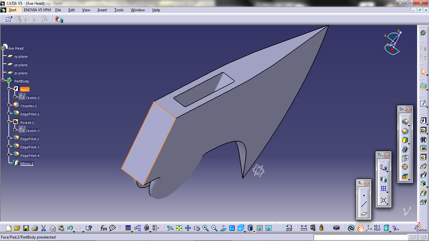
If you have done everything correctly according to this tutorial, your axe head should be like in this picture:

That is all for now. I'll post the tutorial for the axe handle another time. Till then, see ya.
Make sure to check back for future updates in Catia v5 Tutorial for Beginners.


